


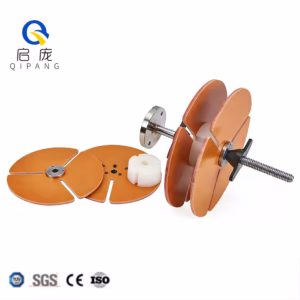
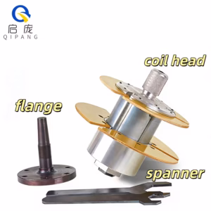
_副本-300x300.jpg)


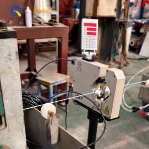
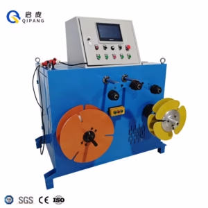
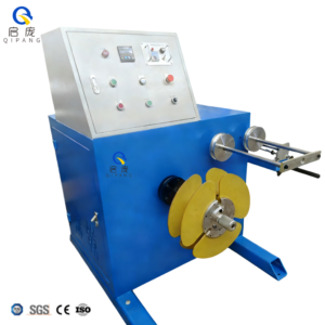
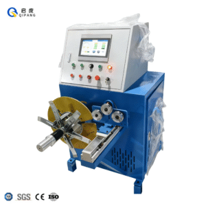
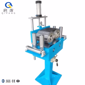
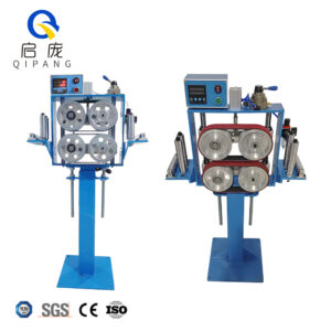
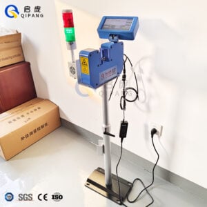
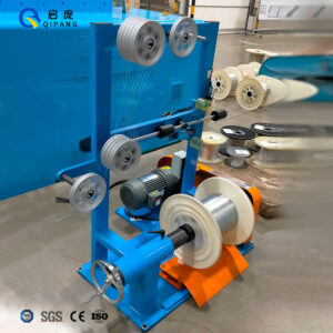
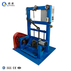
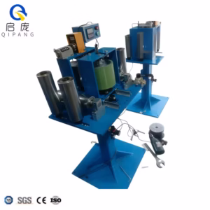
The Wire Cable High-Frequency Test Machine is a vital device for determining the functioning and reliability of wires and cables under high-frequency conditions. This machine ensures that wire and cable products meet strict industry standards, which are now necessary due to technological improvements that demand higher performance levels in electric components. In this article, we will look at what this testing equipment does, different areas where it can be applied, and why conducting tests on electrical systems’ durability and efficiency enhancement through high frequency is important. With knowledge about how it works and its relevance within the sector, one can appreciate the fact that without such equipment, many wire manufacturing companies would not be able to achieve their desired quality standards while at the same time meeting customer needs in terms of safety requirements during usage or installation.
What is a High-Frequency Test Machine?

Understanding the Basics of Frequency Testing
Frequency testing is a method of determining the performance of wires or cables under different electrical signal frequencies. It aims to establish impedance, attenuation, and transmission properties within various frequency bands a cable can allow signals to pass through. High-frequency tests are essential because they reproduce the environments in which different types of cables used for communication systems and transmitting power may find themselves. Engineers use these findings to determine if a given wire is suitable for particular purposes by ensuring it meets the required functional standards and reliability levels after undergoing this type of examination. Manufacturers can also use this test to measure things like signal loss and reflection with special tools, thus giving them the information necessary to make decisions about cable design or material selection based on the evaluation.
Importance of Using Advanced Test Equipment
The usage of highly developed examination tools is significant in testing at high-frequency because it helps to achieve accuracy. To begin with, this sort of equipment makes accurate performance characterization possible by allowing precise measurement under different electrical states of the cable. This preciseness is crucial for the detection of reliability and efficiency problems that may arise during application. Besides that, more advanced test systems are capable of handling wider ranges of frequencies and various types of tests, thus enabling engineers to mimic real-life situations more accurately to understand better how products should be designed or improved upon through thorough analysis. What’s even more important about using these kinds of equipment is that they can help meet standard requirements; hence, people will have faith in the safety standards followed while installing electrical wiring systems.
How to Utilize a High-Frequency Tester for Cable Evaluation

Critical Steps in Setting Up the Test Equipment
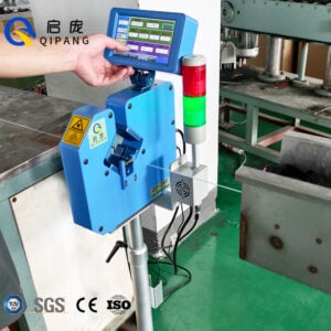
- Calibrate the Tools: Make sure that you have properly calibrated your high-frequency tester in accordance with the manufacturer’s instructions before you start testing. This is very important if you want to get precise and dependable results.
- Connect the Wires: Attach cables to the test ports of the tool firmly, making certain there are no loose ends or dirt that could interfere with readings caused by rusting.
- Choose Testing Parameters: Set up frequencies, time duration and other measurable quantities on this gadget (such as signal loss, reflection coefficient) which should be tested during evaluation based on its goals.
- Conduct Preparatory Experiments: Run a number of initial tests to verify whether the equipment operates well and if the test setup remains stable; for instance, try using a short length of known-good cable as a reference.
- Perform Evaluation using a high-precision testing kit. Use portable kits designed to carry out full-length tests on cables being evaluated. Monitor outcomes in real-time and adjust them where necessary due to environmental conditions or performance mismatches among devices used.
- Keep Records: Take note everything carefully while recording all measurements taken so far since some abnormality might be detected later at another stage thereby compromising accuracy during analysis phase. These records will also form part of report writing process therefore they must be accurate enough.
- Evaluate Results: Once testing has been completed go through recorded data systematically analyzing each set against predetermined benchmarks to determine how well or bad such wires performed.
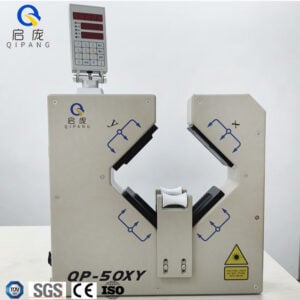
Configuring the Tester for Accurate Measurement
A tester must be set up properly to ensure accurate measurements during an evaluation. Here are some steps to do it:
- Calibrate the Tester: Start by calibrating the tester as per the manufacturer’s instructions. Usually, this involves using a calibration standard in order to adjust readings of the equipment which guarantees accuracy for future measurements.
- Adjust Frequency Range: Configure frequency range so that it matches cable under test characteristics ensuring measurement falls within applicable operating bandwidths and reflects what is happening with the cable accurately.
- Modify Testing Parameters: Enter necessary testing parameters such as resolution and test duration.Selecting longer test durations will help average out any transient responses while higher resolutions allow for more detailed analysis of signal properties.
- Enable Averaging Functions: Where possible enable averaging functions on the tester being used.This will smooth out noise in measurements thereby presenting clearer picture about performance of cables under consideration by eliminating data variability.
- Check Connections: Before starting tests again, check all connections to avoid making mistakes while taking measurements.Ensure that every port is well tightened and there are no damaged cables since these factors may greatly affect outcome accuracy.
If followed closely, these guidelines can make testers give trustworthy and accurate measurements, which are crucial for successful cable performance evaluation.
Interpreting High-Frequency Test Results
In order to understand the high-frequency test results, one must know what each parameter means and how it relates to the measurements made. Signal integrity is a key area of high frequency testing that often gives insights into propagation delay as well as attenuation characteristics of cables.
- Signal Integrity: Evaluate rise time, fall time and whether there is overshoot or undershoot in signals among other things. When these do not meet expectations, this could be an indication for impedance mismatching or issues in connectors caused by excessive inductance or others .
- Propagation Delay: It helps determine the speed at which a signal travels along any given cable. This should be measured against industry standards and specific application requirements.
- Attenuation: Examine the curve showing how much power was lost over different frequencies during testing. A smooth line with predictable drop-offs indicates good quality, while sudden drops may mean manufacturing error at certain points.
Understanding these areas will enable practitioners to evaluate cable performance abilities vis-à-vis use within systems operating at higher frequencies.
What are the Specifications of a High-Frequency Test Instrument?
Essential Specifications to Look For
When you are deciding on a high-frequency test instrument, some important specifications need to be considered so as to guarantee precise and trustworthy measurement outcomes:
- Frequency Range: The device must possess a broad range of frequencies which are capable of accommodating the particular application under consideration; this means looking for minimums that go far beyond what will be used so that all relevant features can be captured with accuracy.
- Dynamic Range: It shows the difference between weakest and strongest signal levels that can be measured accurately by an instrument. Higher dynamic ranges allow low-level as well as high level signals detection without distortion.
- Resolution Bandwidth (RBW): Narrowing down RBWs allows one to differentiate between closely spaced signals, which is necessary when dealing with high-frequency applications. A good choice would, therefore, be a device balancing RBW against sweep time.
- Input Impedance: For each cable tested, ensure input impedance matches characteristic impedance of such cable i.e., 50Ω or 75Ω commonly used values; otherwise reflections will occur leading to inaccurate measurements being made about all cables.
- Calibration and Accuracy: These instruments should be regularly calibrated to ensure they remain accurate throughout their service life. Seek devices with maximum permissible errors specified at various measurement conditions.
- Data Storage and Connectivity: USB ports among other things like Ethernet connectivity etc., help in storing data quickly and easily as well transferring them over long periods thus allowing continuous monitoring of measurement results which might take time before being analyzed especially where there are many tests involved.
By considering these factors, experts can select appropriate HFTE equipment for their specific needs, thereby upholding test reliability.
Choosing the Right Instrument for Your Needs
To select a high-frequency testing tool, you must carefully evaluate your application’s needs. First, determine the minimum signal range and sensitivity required for capturing all relevant signals accurately. Decide on resolution bandwidth by considering neighboring frequencies that should be separated; narrower bandwidths may help in such cases. Make sure there is good matching between input and output impedances to reduce reflection losses while making measurements more accurate. Regulate calibration frequency because this is necessary for maintaining measurement confidence throughout an instrument’s life cycle; therefore, choose instruments with clear calibration procedures and accuracy statements. In addition, appraise storage capacity plus connectivity alternatives that can enhance efficient data management and analysis capability. These points can guide you to decide what suits your particular testing requirements best and guarantee the validity of findings made during tests.
Understanding RF and SMA Test Requirements
In high-frequency applications, it is essential to follow Radio Frequency (RF) and SubMiniature version A (SMA) test requirements to get accurate and dependable results. Common RF tests examine the transmission properties of devices at different operational settings, focusing on metrics such as insertion loss, return loss, and intermodulation distortion. You must ensure that these parameters are measured by instruments whose frequency range matches your application area.
The robustness of SMA connectors makes them popular for many applications; thus, it is necessary to maintain connector integrity during testing not to degrade signals. You should review specifications for your SMA-connected devices vis-à-vis compatibility with test instruments and the correct connector type. One must follow appropriate torque specifications when connecting SMA cables because wrong torques might damage them or affect measurement reliability. Industry professionals can ensure their RF and SMA tests meet accuracy standards if they follow these rules closely.
What Accessories Do You Need for High-Frequency Testing?

Must-Have Accessories for Enhanced Test Performance
So as to secure more precise outcomes during high-frequency tests, it is important that you include some necessary accessories in your testing station. Initially, precision torque wrenches should be used to apply a uniform amount of torque on SMA connectors so as to make sure that they are firmly connected without getting damaged.
Secondly, good RF cables ought to be used since they help maintain signal integrity, whereas low-quality ones may introduce loss or interference. Moreover, attenuators can be useful for managing signal levels and protecting sensitive equipment from overload.
In the toolkit, calibration tools and reference standards should confirm whether your measurement devices are accurate enough and meet industry requirements. Finally, isolation pads or RF absorbers may be added to reduce reflections and external noise, thereby improving test data reliability even further. These accessories will enable you to achieve higher measurement accuracy and greater overall efficiency in conducting high-frequency tests.
Alternative Devices
Optional and Replacement Accessories
A high-frequency test setup can include more tools than those essential. For example, RF power meters measure the output power of a device under test and ensure it is within the required limits. Variable attenuators can also be employed in tuning electronic circuits where signal levels need accurate control during measurements.
In addition, when working with different environments for testing purposes, one may consider using other RF connectors like N-type or BNC connectors, which offer more connection options. It is important to have spare, good-quality RF cables if any show signs of wear or damage because this could affect signal integrity. Also, sensitive instruments should be kept in protective cases that can guard against physical hazards as well as environmental factors, thus contributing to their durability as resources for testing activities. These are some of the optional things that can be added into a setup by professionals who want to achieve better test outcomes by tailoring them according to specific requirements.
How to Download and Use the Manual for a High-Frequency Tester

Where to Find the User Manual
Normally, the consumer manual for a high-frequency tester is located on the company’s website under support or downloads. It is recommended that you search by the device’s model number to make sure you get the right manual. Moreover, many companies have PDF copies that can be downloaded for offline use. If you bought the item from a retail store or authorized dealer, they may give you a hard copy. In case all of these solutions failed then just contact their customer service and ask them where I can find a user manual for my high-frequency tester.
Necessary Specifications in the Manual
To guarantee that the high-frequency tester manual is efficient, it should include several essential specifications. In general, these are some of the key specifications often detailed in the user manual:
- Frequency Range: The range within which measurements can be done by a device accurately, usually given in megahertz or gigahertz.
- Dynamic Range: This shows how sensitive and capable an instrument can be of capturing weak signals as well as strong ones based on the amplitudes it has been designed to measure.
- Input Impedance: The impedance value measured at ports where tests are carried out, usually 50ohms or 75ohms, depending on whether you want matching between source and load during testing or not.
- Calibration Information: This section should also include frequency calibration intervals recommended for maintaining accuracy during the measurement process and procedures used in calibration.
- Environmental Specifications: Different environmental conditions, such as temperature ranges under which performance remains optimum, need to be indicated here, together with humidity levels allowed for operation.
- Power Requirements: Voltage/current ratings needed for safe, effective working conditions power inputted into a tester must never go below certain standards; otherwise, it may not perform its functions accordingly.
Familiarity with these specs enables professionals to make informed decisions when selecting their high-frequency testers, which increases reliability during test execution.
Step-by-Step Guide for Proper Tester Operation
Verify Frequency Range: Make sure that the frequency of the signal being tested is within the frequency range mentioned by the tester.
- Check Dynamic Range: Look at how high and low the signal goes to see if it falls within the dynamic range of measurement devices that can measure accurately.
- Match Input Impedance: Check whether input impedance on your tester should be 50 ohms or 75ohms for better matching with source and load thereby ensuring integrity of signals.
- Calibration: Follow manual procedures for calibration so as not to miss any steps which may lead into faulty readings later on when using this equipment.
- Monitor Environmental Conditions to maintain accuracy of your measurements.: Ensure that you are working under specified temperature and humidity ranges because these can affect other factors thus interfering with your results.
- Confirm Power Requirements: The power supply must match what is written in terms of voltage ratings, etc.; failure to do so might damage some components while using a voltage higher than recommended or even worse, provide less current than required, hence affecting overall performance, especially during heavy loads.
Following these steps will ensure the safe, proper operation of the high-frequency tester.
Reference Sources
Frequently Asked Questions (FAQs)

Q: What is a high-frequency test machine for wire cables?
A: A high-frequency test machine for wire cables, or Wire Cable High-Frequency Test Machine, is a specific instrument that measures the electrical performance of wire cables with respect to insulation resistance and return loss over an extensive frequency range. In order to get accurate readings, several parts, such as a spark tester, analyzer, calibration unit, etc., are included in it.
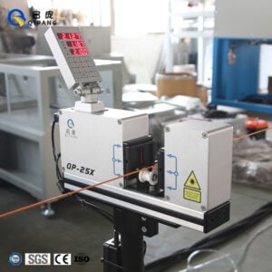
Q: How does the spark tester work at high frequencies?
A: It applies high-voltage signals on wires and detects sparks that indicate faults; then, it captures these failure points automatically using detectors so that the cable meets better quality standards.
Q: What should I know about the product when buying it, as well as its features?
A: Some essential characteristics include the ability to test both AC/DC modes, port configurations, voltage/current ranges, frequency domain (MHz—GHz) covered by the specific model type selected, wireless interfaces for remote control and data output, etc.
Q: How can this machine be used in wire cable diagnostics?
A: Collecting different diagnostic information like insulation resistance values, return losses, or even frequency specifications across various bands helps a lot in pinpointing where exactly the problems are located within these cables, thus increasing their dependability.
Q: What is its voltage range?
A: Depending on the model chosen and application being performed, they are designed accordingly with different voltage ratings making them useful components of any multifunctional kit. Usually such machines are capable of testing under HVAC & HVDC conditions so that compliance with necessary standards can be ensured.
Q: What kinds of cables can this machine test?
A: It can test different cables, such as coaxial, antenna, and multi-conductor cables. It is also designed to handle various cable diameters and lengths, which makes it an all-around tool for electrical engineering applications, especially when used alongside a portable kit.
Q: Does the machine ensure accurate measurement?
A: Yes, this device’s software is advanced, enabling it to make very accurate measurements during calibration. For instance, it can accurately detect resistance with high precision, frequency domain characteristics, and spark testing outcomes.
Q: In what ways does this machine save time during tests?
A: The machine has quick diagnostic tools built into its system; these, combined with automated features, including automatic calibration and data capture, help in speeding up tests, thereby reducing manual intervention greatly, which eventually results in a shorter test duration.
Q: Can one perform remote diagnostics using this machine?
A: Yes, some models come with wireless capabilities that enable remote diagnostics. This is particularly useful when you need to collect data or operate the device from afar, as it makes the equipment more flexible for different scenarios.
Q: What does the frequency domain testing capability mean for the machine?
A: With frequency domain testing capability, the device can assess cable performance across a wide range of frequencies. This is vital where accurate high-frequency characteristics are required for applications so that they can work optimally under real-world conditions.